|
|
 |
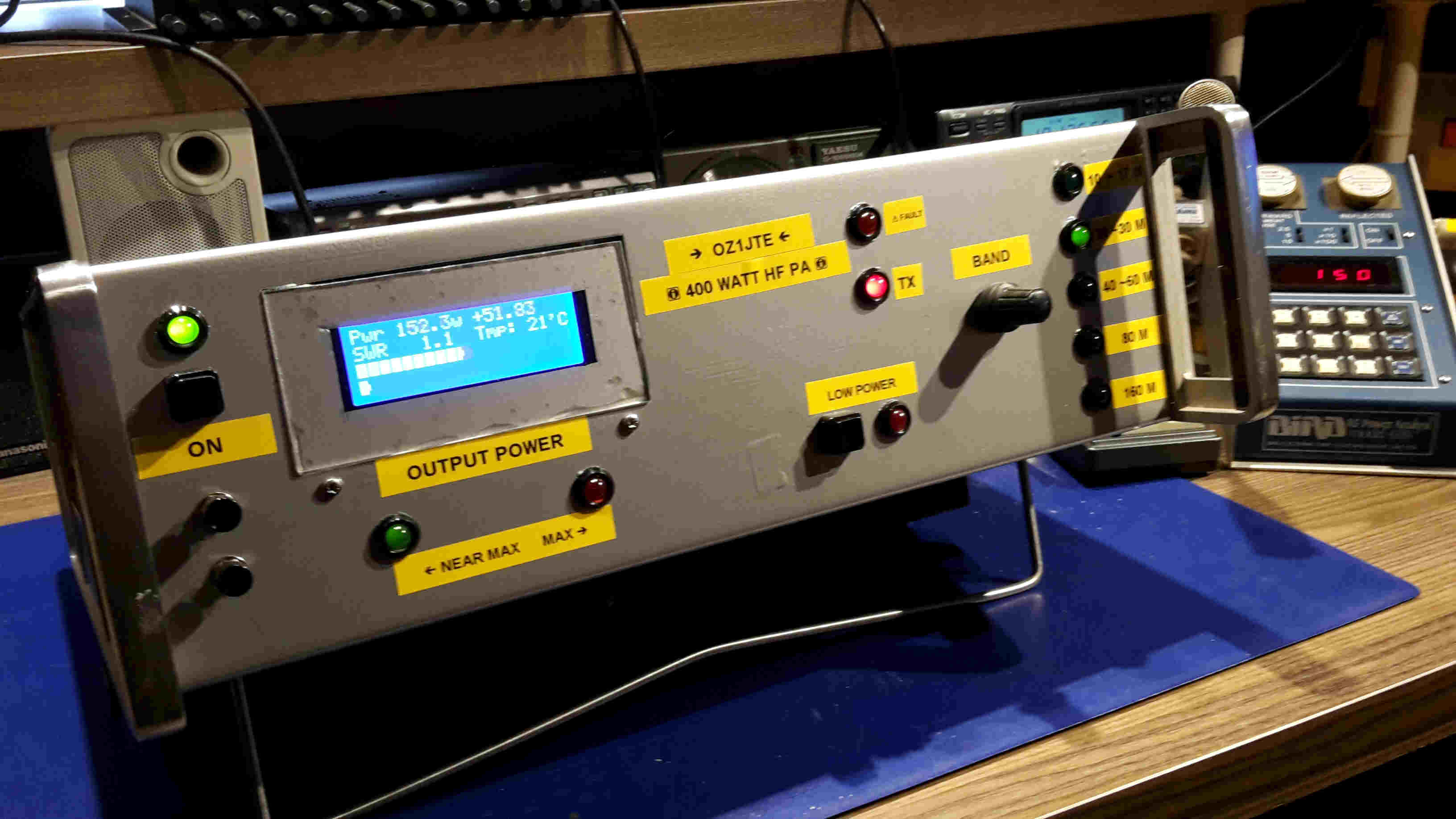
Homebrew 400W HF Power Amplifier for HF, made out of old Skanti Parts.
By Thomas Gosvig OZ1JTE, Denmark.
 |
 |
|
|
From Idea to reality.
From
time to time you will find old Marine SSB HF radio systems for sale.
Many
of the radios are taken out of service these years because of new Marine
regulations etc.
You
often meet old systems because of this at flea market and sometimes get an offer
to have it for free.
In
my local Ham club we were lucky enough to get a pile of older Skanti parts and
also complete systems and of course I wanted to bring some of this fine
equipment back to life.
I
chose TRP-8400. A 400W HF SSB system.
You
will find these systems as 250W, 400W and as 750W. Skanti TRP-8250, TRP-8400 and
TRP-8750.
I
knew from earlier projects that this was a very rugged system made back in the
early 80’ and was also made for heavy Telex duty.
Therefore I decided to use some of the modules from this system to make a Ham
friendly Power Amplifier that easily would interface to any Ham radio.
I
wanted the ability to use both lowpower and 100W transceivers as exciter to
bring the PA up to full power at 400W.
I
got the Power module, Lowpass filter, 48V smps and a directional coupler ot of
the TRP-8400 transceiver and then started to make some design thoughts.
You
will on this page get an impression of the project and I hope it maybe will
inspire you to start your own project.
 |
 |
 |
|
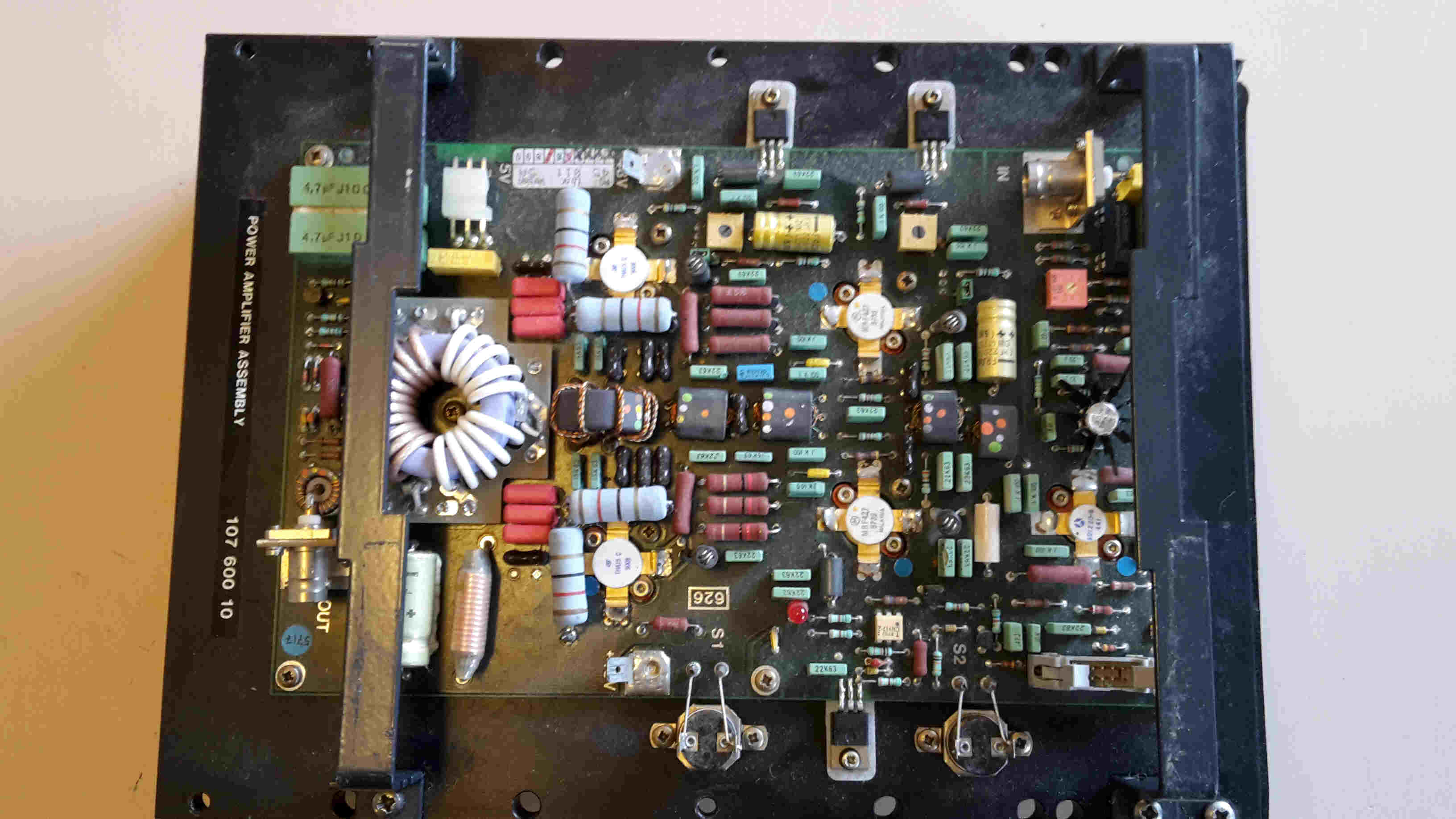
| Skanti 250W PA module. My 400W module is shown a bit down at this page |
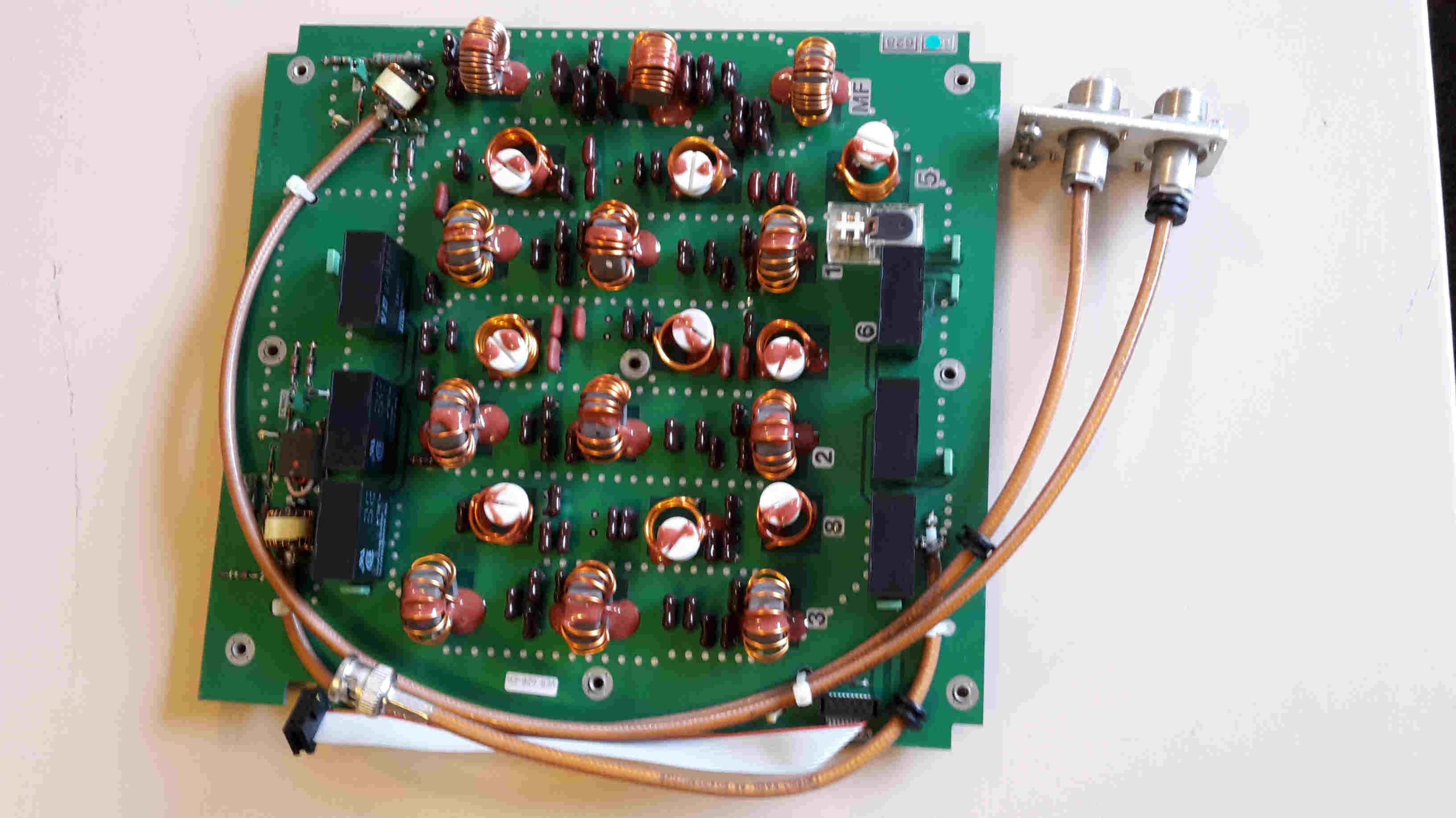
Skanti Lowpass filter. This one with 500 KHz filter (pcb628) | Directional Coupler from the Skanti Antenna Tuner Unit. |
Some thoughts about the design.
To make
the PA as flexible as I could my design ended up with an attenuator outside the
box so you are able to make this attenuator fit the output of your transceiver.
Anything will do if the input to the PA not exceeds 35-50 mW.
The gain
in the Skanti power module are about 42 dB so you see that it doesn’t need much
power to give full rated output.
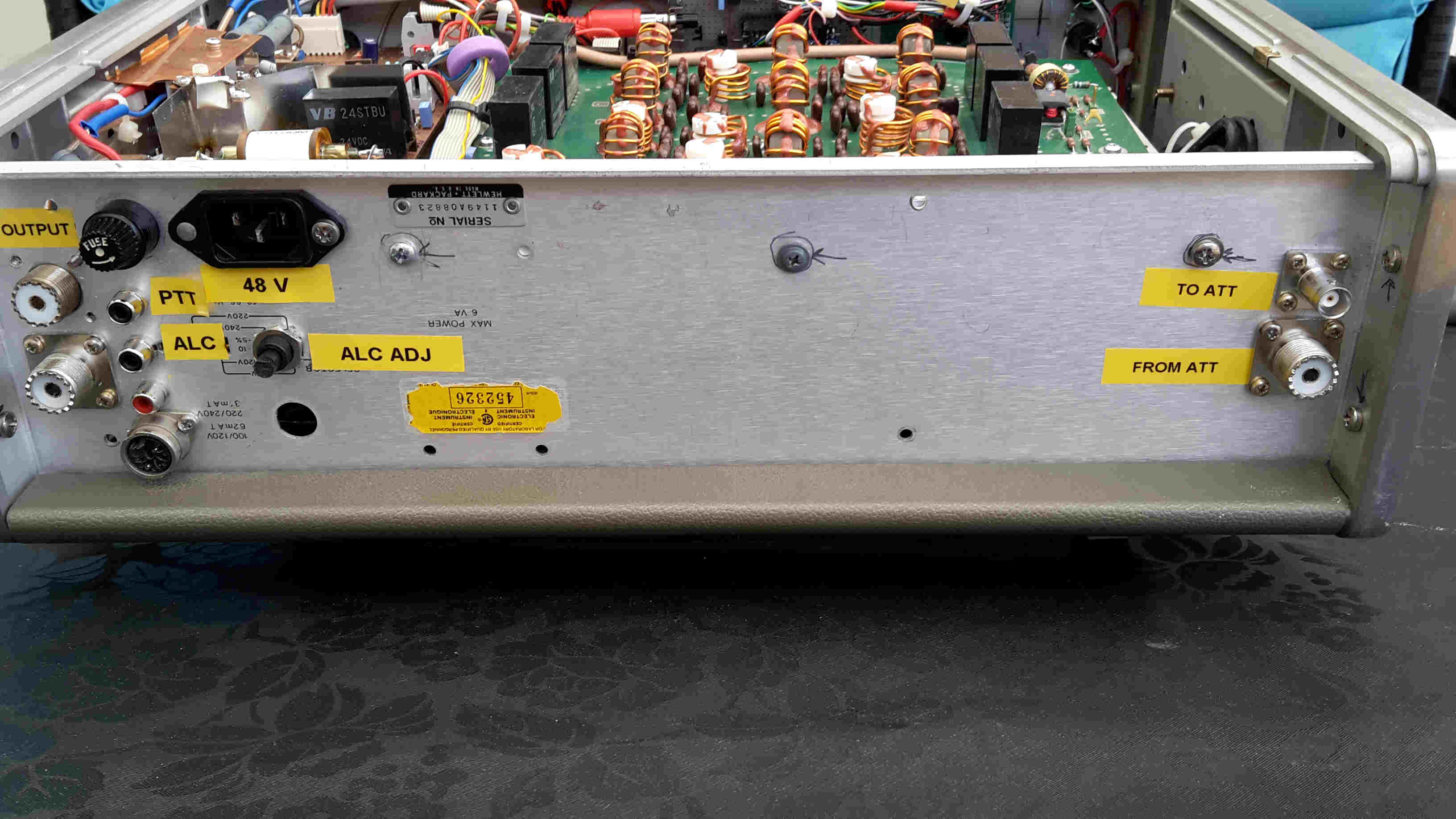
At my
back panel of the box I then made 2 RF sockets. One called “To Att.” And one
called “From Att.” and when my 100W
returns from the attenuator I have 35 mW left I use to feed the PA module.
As you
can calculate my attenuator attenuate 34.5 dB.
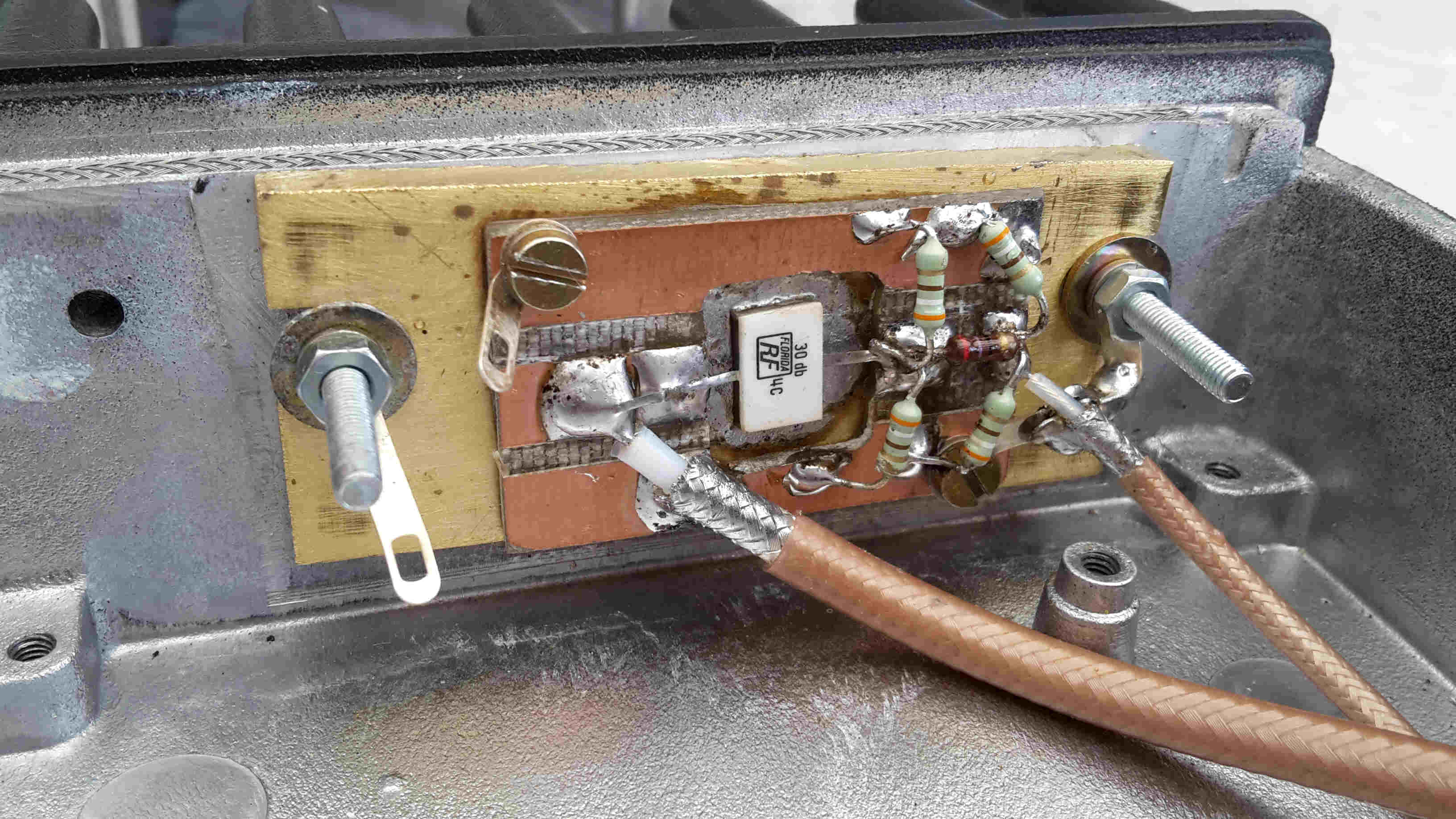
I made
the attenuator out of a little 30 dB “Tap and Cover attenuator” from RF Laps and
then made my own 4.5 dB from standard 1/3 W resistors.
You will
see at my picture that the attenuator was put inside an old Skanti VHF radio
chassis that already had a big heatsink.
 |
 |
 |
|
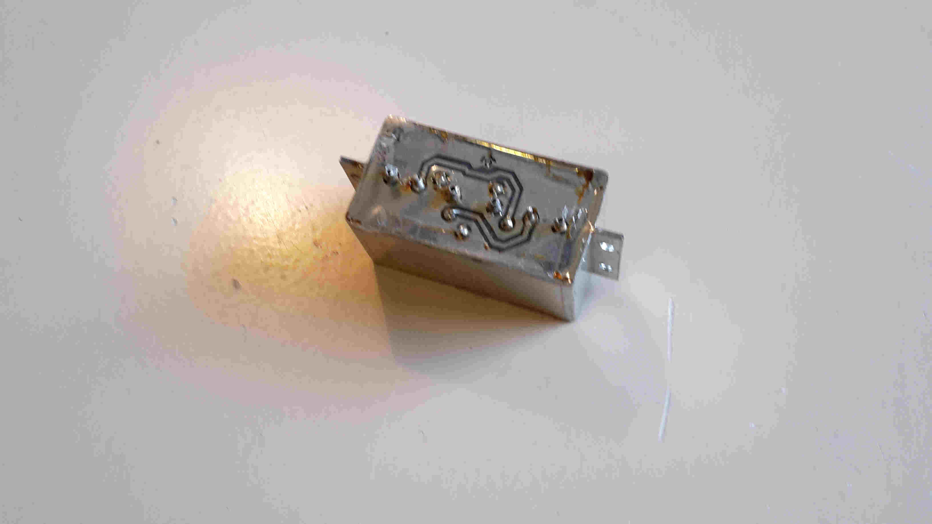
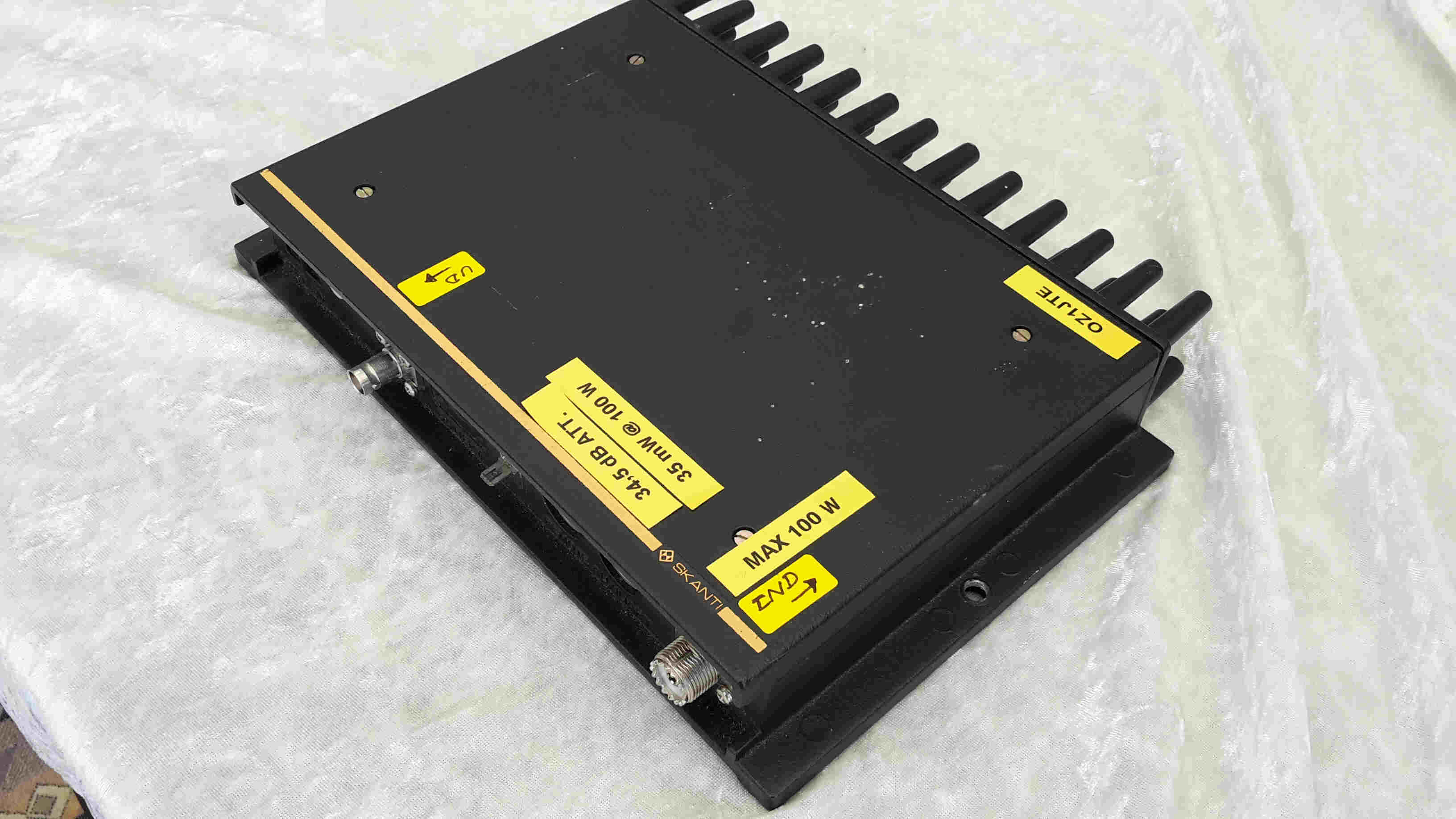
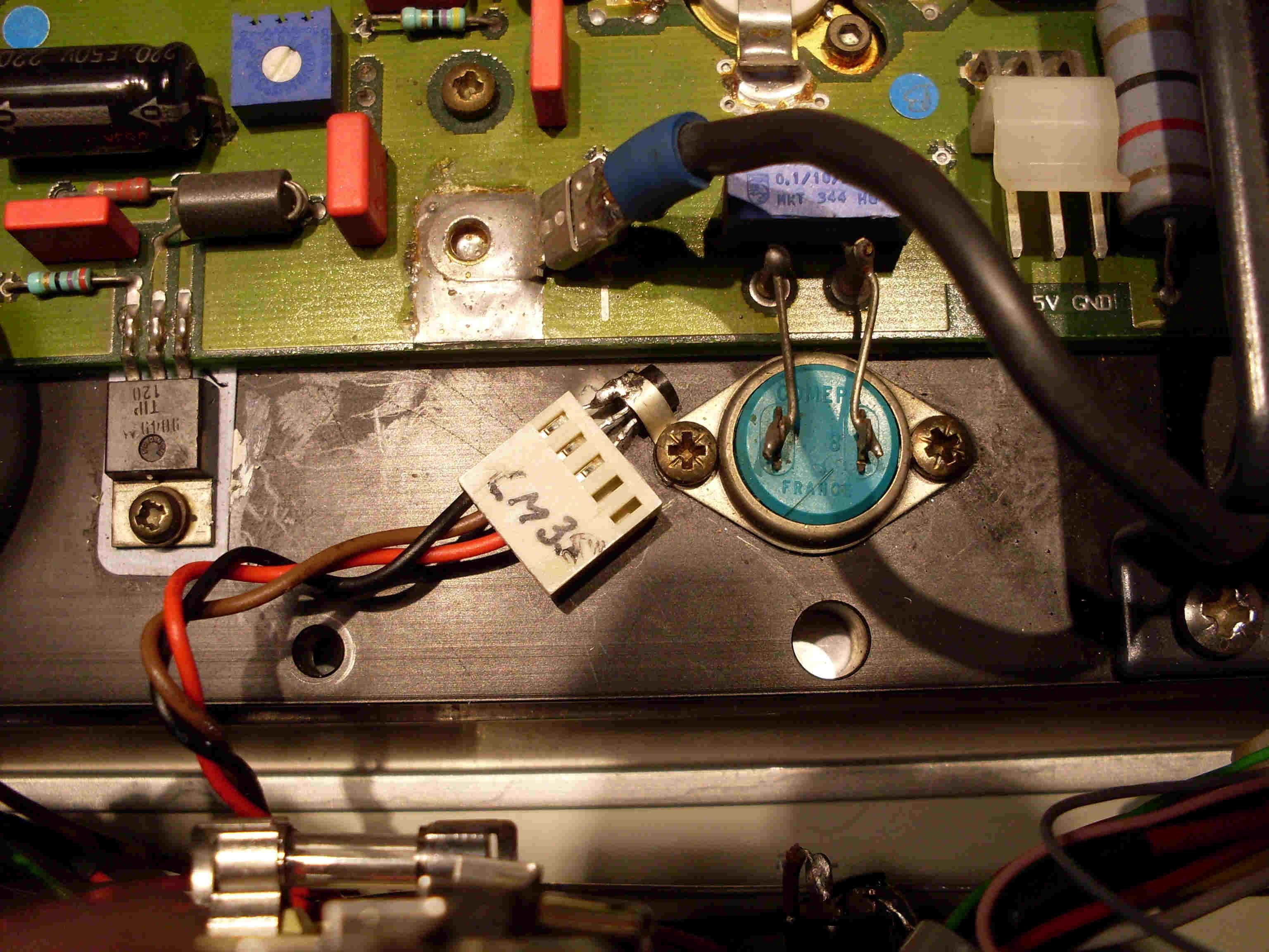
| 34,5 dB Attenuator. 35 mW out @ 100W in. | 30 dB Chip resistor + 4,5 dB from 1/3 W resistors | LM35 Temperature sensor close to the PA Heatsink |
|
|
 |
|
|
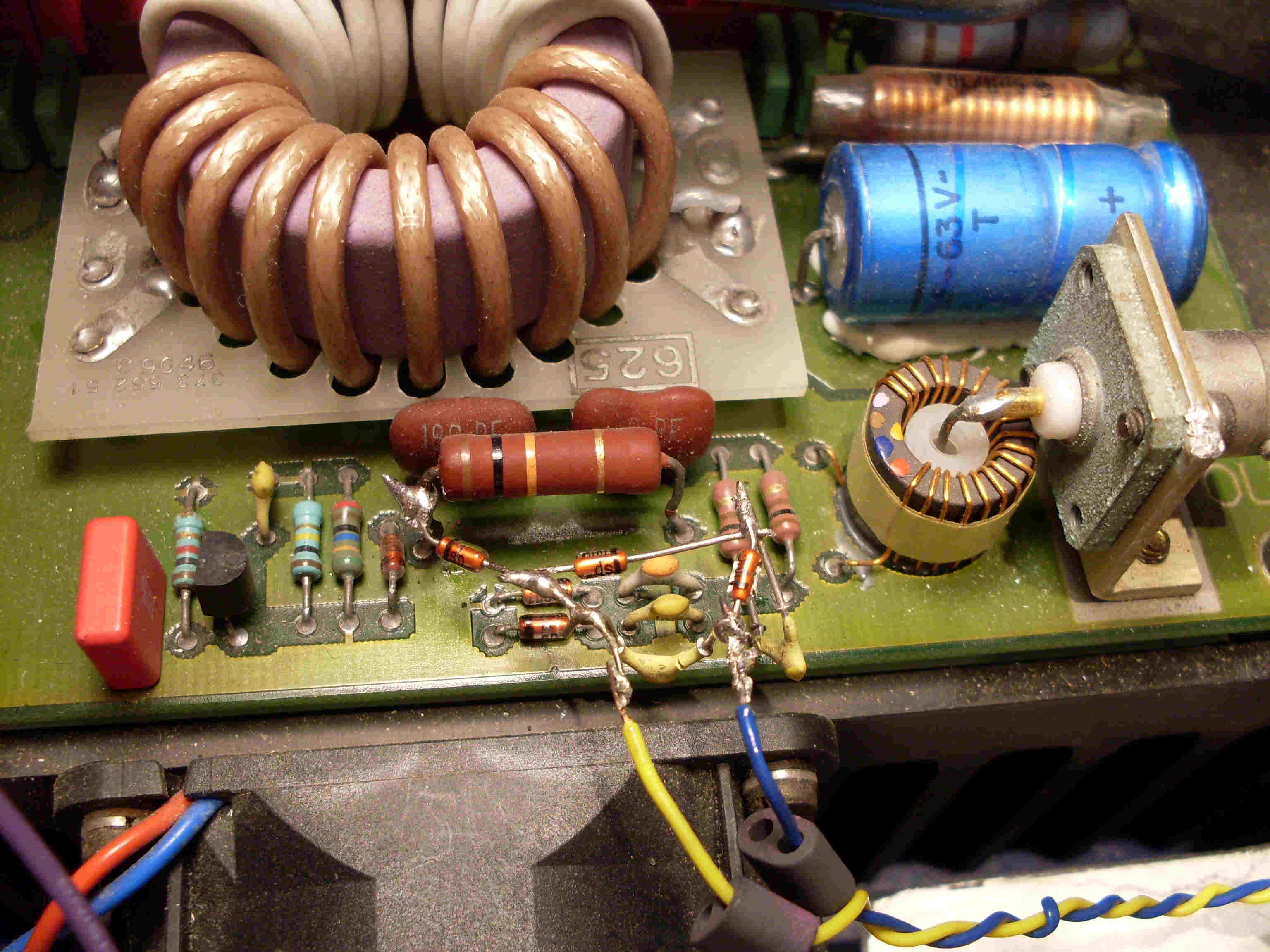
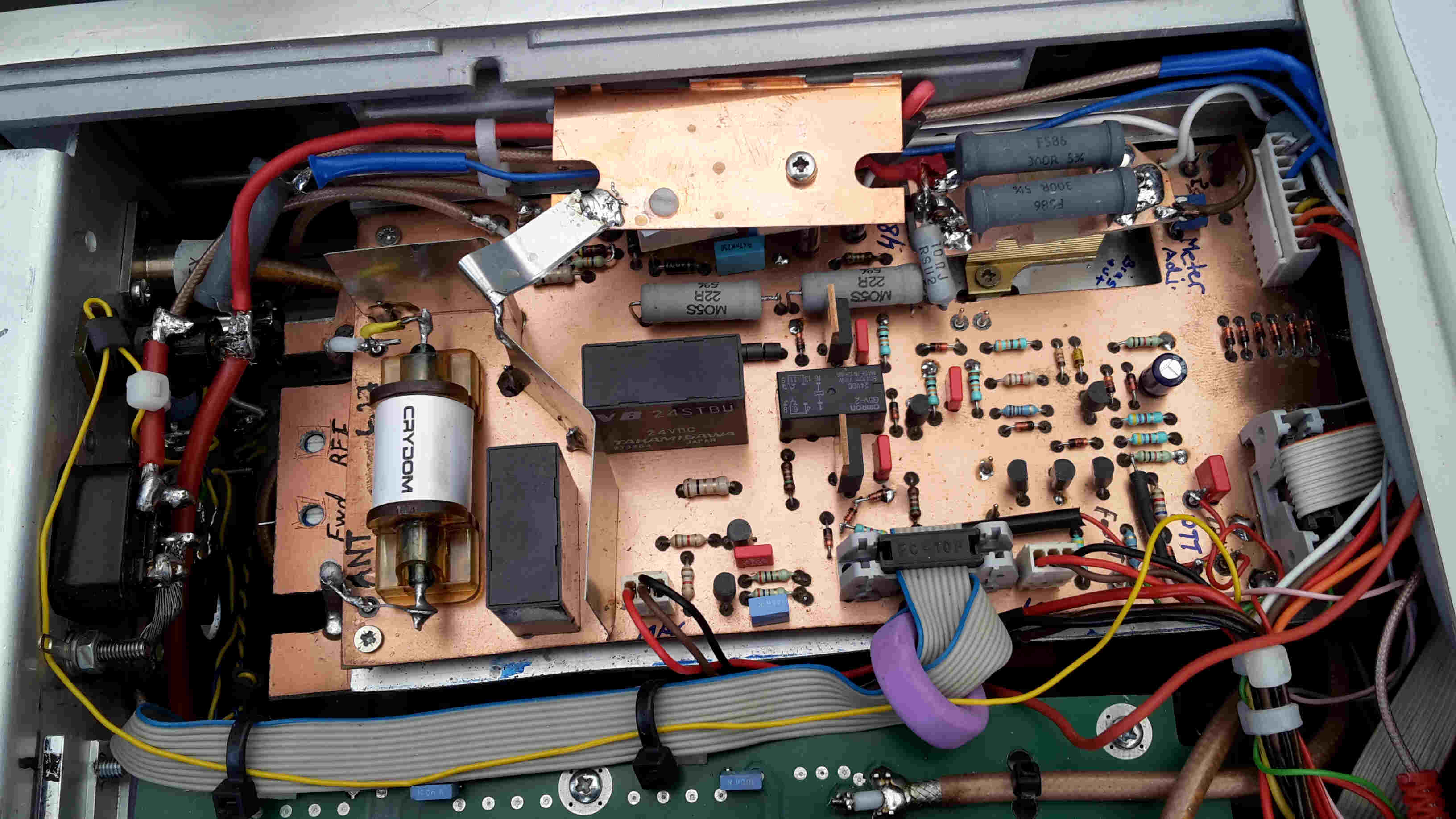
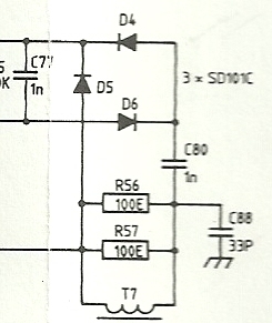
Homemade ALC detector directly soldered on top of the original one. |
Make a new negative going ALC output. Just copy the parts D4, D5, D6 and C77 and C80, and solder it just like the original parts at R56. REMEMBER to reverse the diodes. The voltage on your "new" C77 is now the negative going ALC voltage for your transceiver. |
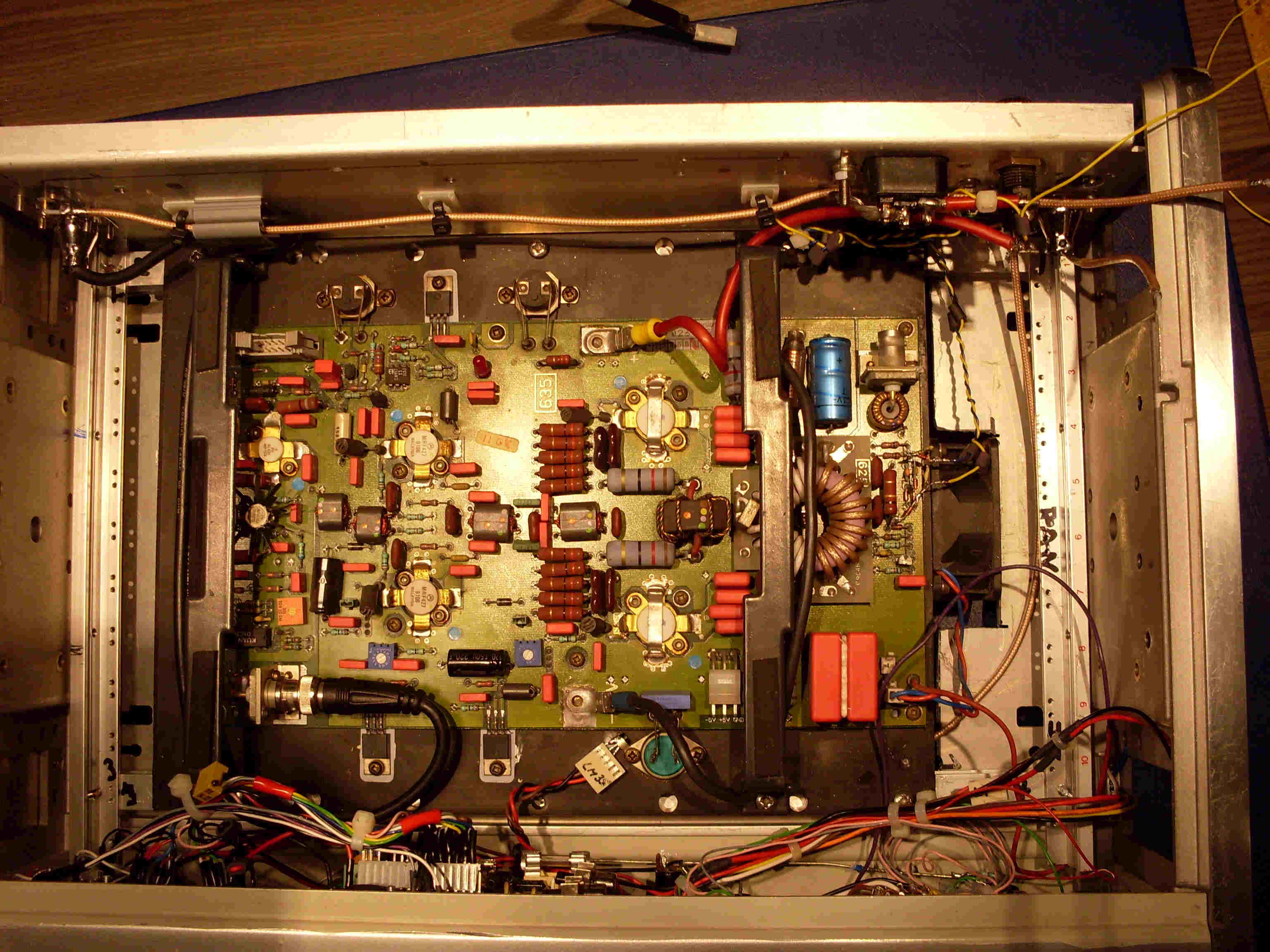
The 400W PA module sunk down in the box. Just before the Lowpass filter is put in. |
On the
Skanti Power module you will find a detector(Power+SWR) that monitor these
signals and are able to internally close down the module if these signals
exceeds a certain level.
What we
have to do ourselves then are some relay shift, a sequencer to control the
different control signals and then also we need some voltage regulators to
produce the needed DC supply's.
48V for
the output devices. A not critical bias supply, 24V and also 12V to supply the
rest of the circuits.
To make
these DC voltages a simple way I use some power resistors to burn some voltage
of the 48V and then let this lower voltage feed the 24V regulator and the Bias
input at the Power module.
The
Skanti schematic says 7.5V for the internal Bias regulator and I feed this pin
with between 31V and 3V depending on how hard you drive your amplifier.
More
drive will result in more bias current and more voltage drop..
This big
voltage drop are realized by a 40W resistor.
A flange
mounted 25W resistor at 82 Ohm and then 2 times 300 Ohm 7 W parallel to the
first one.
This
result in a 40W resistor at about the needed value of 56 Ohm or so to make the
needed voltagedrop for the bias input. On the PA module you will find a voltage
regulator making the final
biasvoltage and regulation to feed the devices.
|
|
|
|
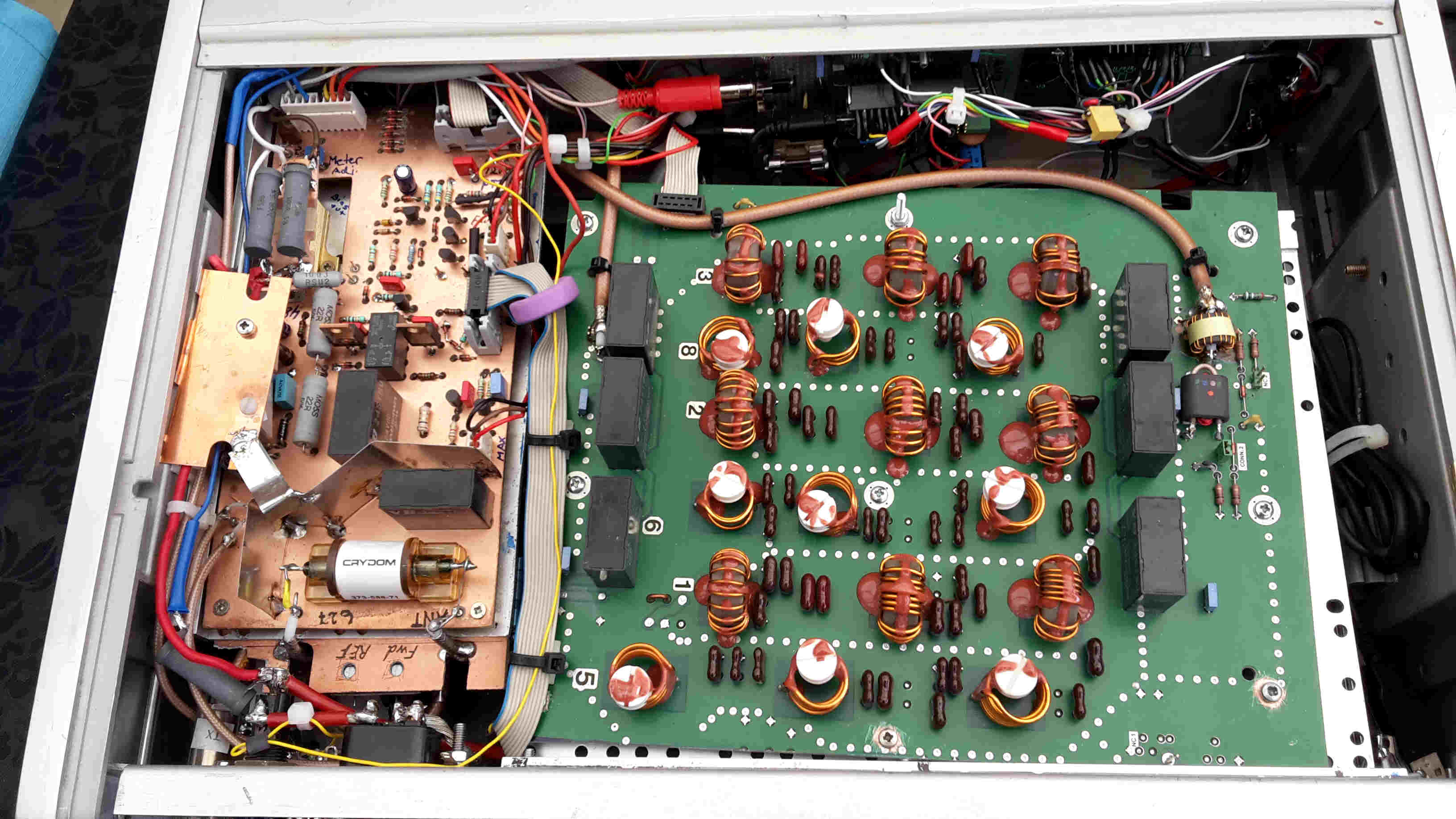
A final look down in the box. |
A look at the homemade Controllerboard. Check out the cooling and the Pwer resistors. |
Control board, and sensor voltages.
As you
see in my schematics I try to take care of most things at my Controllerboard.
All
communication back and forth to the PA module and the Lowpass filter I do
through the two standard 10- pin Molex connecters.
I don’t
find much to say about the Lowpass filter.
I
control the settings of the relays through a diode matrix giving the right 4-
bit code to control the filter to the right band depending of the setting of the
bandswitch at the front panel.
Internal
on this Lowpass filter you will find a “Peakdetector”.
This is a detector that gives a value between 0 and about 9V dc depending of the SWR and Power.
Be aware
of the 2 signals(SWR and Power) are “Or’ed”(merged) to produce this voltage.
I don’t
use this voltage myself but have led the signal to a phono socket at my back
panel through a potentiometer. If you like to drive a kind of analog or digital
meter you can use this signal on the control board.
The only
modification I have made on the PA module are a little extra ALC detector
similar to the one already found near the output BNC socket on the module.
This is
necessary because we will need a negative going DC voltage between 0 and about
-4 volt to control the output from our transceiver, so we make sure never to
overdrive the PA.
The
difference between this ALC detector and the one already found at the PA board
are the diodes are reversed.
The ALC
voltage already found at the PA board are positive going and is used internally
for the shutdown circuit.(0- +10V depending of power and swr)((We also use this
voltage later on to start flashing 2 LEDs on the frontpanel to indicate the PA
are “Near MAX” and has reached “MAX”.
To make
our own ALC output we therefore need a similar circuit (5-6 components) mounted
on the same place at the original components(R56), but remember to reverse the
diodes.
Our new
homemade ALC is then led to a Phono socket at the back panel through a 47K
potentiometer.
In a
document in the Download section I have tried to explain all the signals led in
and out of the Power module through the 10 pin Molex connecter.
|
|
|
|
My choise of back panel. |
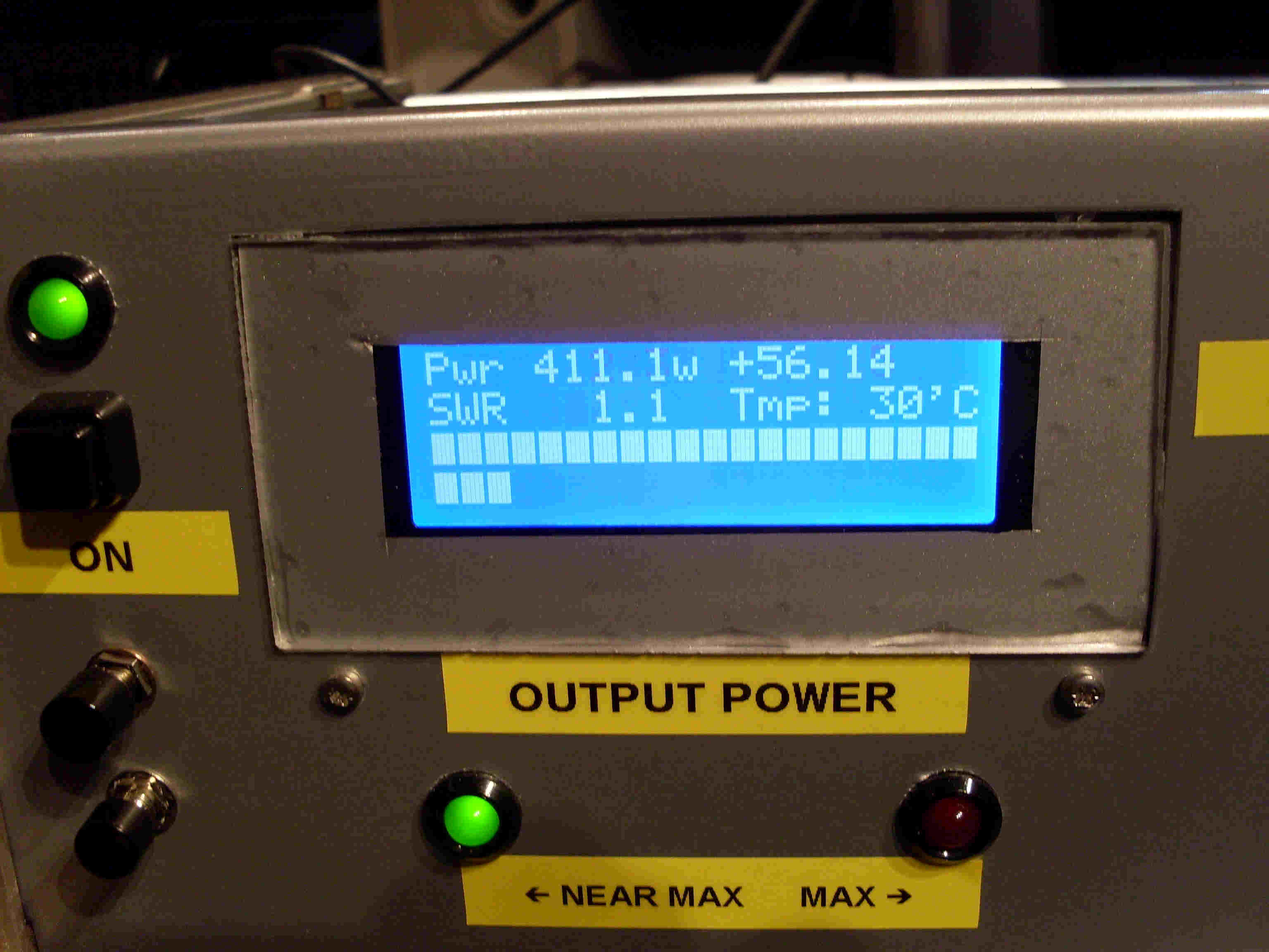
The Arduino Nano controlled LCD Display. |
Power, SWR, dBm, PEP and Temp. Readout.
At the
beginning of this project I first planned to use the filterpeak information to
drive an analog meter at the front panel, but as the project progressed I wanted
to do it a bit more fancy.
Therefore I also build an Arduino based Power/SWR meter and made it a cool part
off the amplifier.
Because
I wanted to do it this way I needed two separate signals. A Forward power
voltage and also a Reflected power voltage.
I used
the little directional coupler from the Skanti Antenna tuner unit. This
component gave me the two needed signals, and after making a stable DC voltage
out of these outputs using a BAT43 rectifier and some smoothing done by a 4n7,
then the signals could be led to the Arduino pins through a 47K potentiometer
for easy adjustment. The Skanti directional coupler has a coupler value of 24 dB
and this means about 7V @ 400W. The Arduino inputs only accept up to 5V so a
voltage divider are also needed.
If you
want this Arduino solution you should have a look at the ON7WQ homepage.
My code
is based on his original code. I wanted a bit more than ON7EQ’s code would
offer, so I made some code of my own to make a input for a LM35 temperature
sensor and also because I used a 4 row display instead of the original 2 row
display, I also wanted 2 bar graphs at the last 2 rows that showed Forward Power
and Reflected Power.
The code
from ON7EQ was already able to show Power, Swr, PEP and dBm.
If you
think this Arduino meter is a little scary, then maybe I should tell you that I
never had made any code myself before I started this project.
A little about the mechanics.
Everything was built into an old HP distortion analyzer box and just as always I
almost ran out of space.
The
heatsink from the PA module itself extends underneath the bottom plate of the
chassis to make sure the cooling is sufficient.
On the
400W Power module you also find a fan that’s start at 50 degrees Celsius (122 °
Fahrenheit)
“Reset”
of the front panel text was made by a kind of foil. I think the foil I used was
the same someone paste on cars for different purposes.
By the
way I don’t mind it’s easy to see you made it yourself.
Feel
free to do it more sophisticated.
I hope
the pictures and the schematics will give you an idea of the rest.
I hope
it maybe has giving you some thoughts about the way you could make your own
project, using some of this oldies but goodies stuff.
I think
this amplifier easily can match all the very expensive ones on the market to
day.
... a few words about the electronic part.
The 2
voltage regulators supplying 12V and 24V to the system needs a good heatsink or
should be mounted on a chassis part.
You will
find 2 pins on the control board that is led to 2 LEDs that indicate “Near MAX”
and “MAX”.
These
LEDs are a fast responding output indicator that shows by the glowing LEDs that
you have reached a certain power level. It can vary a bit from band to band.
The
voltage for these LEDs is taken from the internal ALC voltage at the PA module.
The same voltage that forces the PA module to shut down if the voltage goes
higher than 10V or so. The voltage varies between 0 and 9V regarding to Power
and especially SWR.
Video presentation.
I made a little video if
you like to see it in action.
(BTW: If you got a "QC" label on your Skanti Product and it says "TG" then Guess Who?..:-) )
Bibliography:
1. ONEQ homepage. The original Arduino SWR/Powermeter site.