|
|
|
|
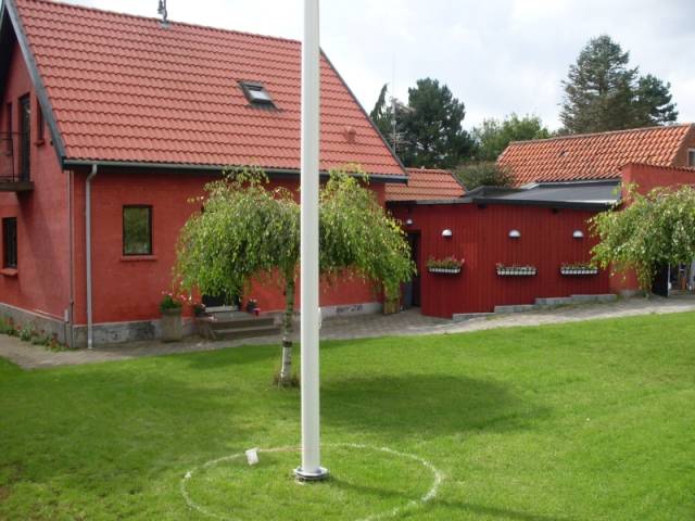
After I have been using a dipole for 80m up about 33 feet in a tree in my backyard, I decided to go back to a vertical antenna, I had used before with good results. The 80m dipole was also the only 160m antenna I had when I feed it like a “T” antenna trough a antennatuner at the bottom of the vertical part of the feed line. When I used the vertical setup some years ago, it was only a setup I put up just before a contest or a major Dxpedition, but this time I wanted a more permanent installation. It was also started to give me some big problems when the 17m high vertical should up in the vertical position, because of the threes in the backyard was taking up all of the place this antenna needed when it was on the ground. The idea of a new vertical antenna was to make it an invisible installation, because I already has a lot of aluminium in the air at my QTH, and I decided to take a little regard to my neighbours blod pressure. I decided to make the vertical 36 feet’s high when it was “standard”, and I also needed to have the possibility to extend the vertical part of the antenna up to something that would come close to a full quaterwave on 80m. This was about 51-54 feet, and if I could achieve this height, I believed that I would have a much more effective antenna compared to my current setup when working DX, and this made the effort pay of in a nice way. At the same time, it was a good opportunity to show that making a invisible antenna in a little downtown garden with a lot of restriction could be done. Furthermore it would be a pretty effective antenna. After making a little planning of the project, I purchased a 12m high fibreglass flagpole, and I had the “full packet” with a nice tilt over fastening at the bottom, a big flag and nice red top and a flag line. The barging included putting up the flagpole at my garden, so that part was easy. |
|
The Project: |
|
|
|
The Flagpole and the start at spring 2008 |
|
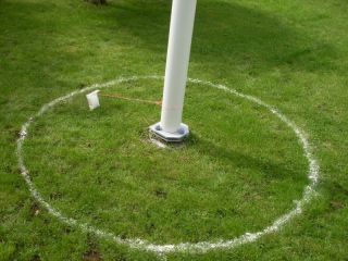
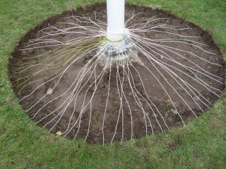
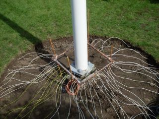
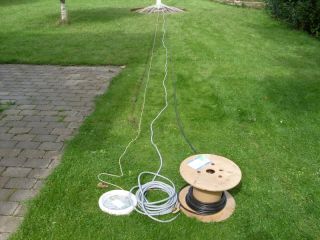
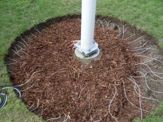
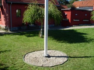
Most people who have read about verticals know about the very important ground system you have to make, to achieve an effective antenna system. Lot of literature describe this issue, but when you are living in a little property and only have about 800 m2 (8.600 sq ft…I think), then you have to face the reality and just do the best you can when making your ground system. I was able to lay down 60 radials. I used 600 meters (1800 feet) of wire. The longest radials were 54 ft. and the shortest of the radials were only 12 feet’s. The main parts of the radials have a length of 33 feet before I ran out of space. Because I had made some grounding systems before for my 160m “T” antenna, I knew that it was important to have a fairly amount of space around the feeding point of the antenna, when I got to the task of making the connection of all the ground wires to the LC network placed at the feed point of the antenna. Because of this I moved 10 inches’ of the soil, in a 6 feet diameter around the feed point. This gave me the opportunity to make a good solid cobber frame for the wire connection, and also let me spread out the radial wires a bit before the first slot with the spade. |
|
|
|
|
A rope and a bag of flour mark a circle. |
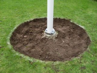
A bit of digging make the room for the grounding installation. |
|
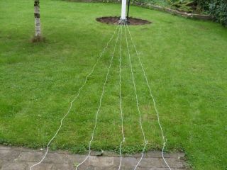
Putting down the radial wires in the lawn is pretty easy, but take up a big amount of time. The wire I used was AWG 15, and I used a plane screwdriver to put the wire down, to just under the surface of the lawn. Do not cut the wire before you reach the end of your slot, as you will find out that you are using about 3 feet of extra wire in a 30 feet slot. This is because of a little zigzag under the surface of the ground. After 3 days and a couple of bladders, I was able to stand up again and take a look at my 60 radials, and the best ground system that I had ever done. |
|
|
|
|
Making the first test of how to do it |
1800 feet of wire distributed into 60 radials. |
|
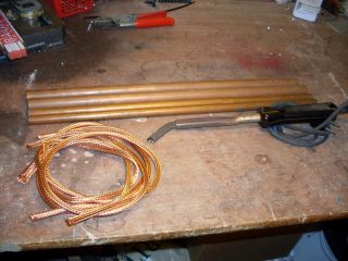
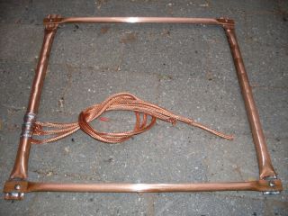
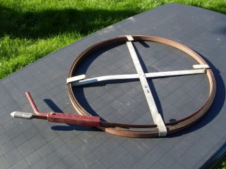
The way I have connected all the ground wires can be seen at the pictures. I made a cobber frame out of some cobber pipes, and this made the handling of the wires easy. A big solder iron and some patience made the job. |
|
|
|
|
Pieces for the ground frame |
Ground frame assembled |
|
|
|
|
Soldering wires to the ground frame |
Lot of wires. |
|
|
|
|
Ground frame all done |
Last slot in the lawn for coax and controller cable(option). |
|
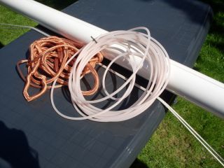
The way I have connected all the ground wires can be seen at the pictures. I made a cobber frame out of some cobber pipes, and this made the handling of the wires easy. A big solder iron and some patience made the job. The next thing to do, was mounting the top wire trough the hollow flagpole. I split up some old RG-213 coax cable and I used the conductor and let the first insulation stay on the cable, to prevent flashover inside the flagpole. It was not easy to put the wire inside the flagpole, because it seems that the manufacturer had used some thin plastic foil in the process of making the flagpole. I found a nice and easy way to do the trick. I don’t know what the name is for this gadget, but it is a piece of tool you use when you clean your sewer. You can see the tool in one of the pictures. With this tool it was very easy to put the top wire trough the long flagpole.. |
|
|
|
|
RG-213 as topwire |
"Sewer cleaner" was a perfect topwire tool. |
|
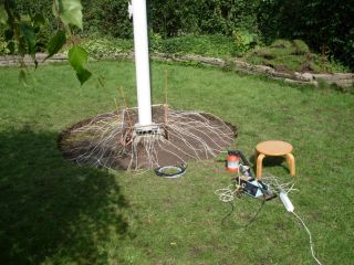
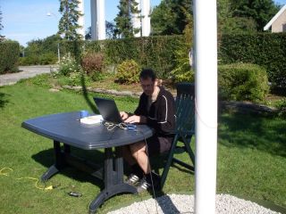
Now it was time to measure the complete antenna system, and I connected my little handy miniVNA to the feed point, and made a complete list of Z, X and SWR and so on, for all of the HF bands below 30MHz.. |
|
|
|
|
The author and his miniVNA measures the system |
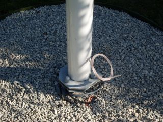
The topwire at the bottom of the flagpole. |
|
Very luckily the Ľ wave resonance was right inside our new HF band 60m. At 5.3Mhz I measured the VSWR to be 1:1.7 and the impedance was 33 ohm. Right now I have started the easy way. I put an automatic antennatuner at the bottom of the antenna. This setup gives me the ability to tune up on every band on HF very quick and easy. Of cause I will design a LC network for at least 80m and 160m, but first I will find a easy way to put the extra 15-18 feet on top of my new flagpole. I haven’t decided yet how to do it, but maybe I will use an old CB antenna made out of fibreglass. It should be an easy job to design some LC network when I measure the full-length antenna with my miniVNA and after this uses the result in the ARRL software TLW.. |
|
Making the project nice and clean |
|
|
|
|
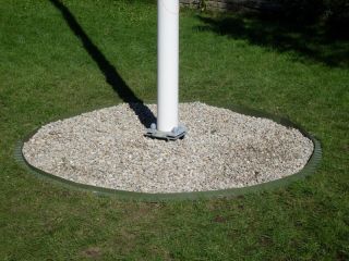
Protection of the wires. |
More nice things to beautify |
|
|
|
|
Nobody knows..... |
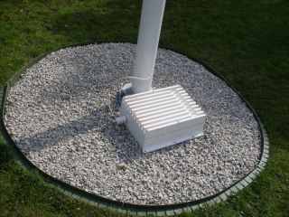
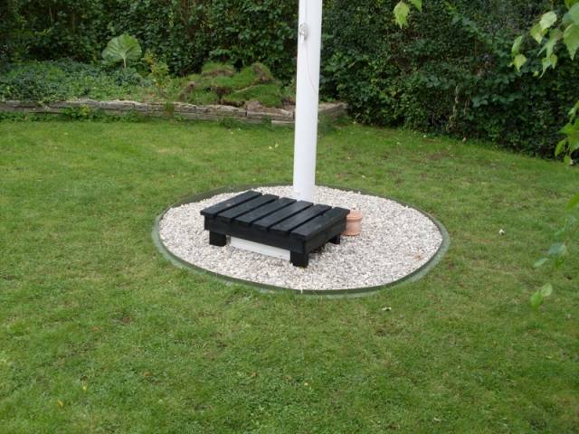
The antennatuner at the feed point. |
|
As you can see at the pictures I made some effort to get the system to look nice after everything was in place, and I believe that the mission was accomplished. I made a little bench to cover up the antennatuner.
|
|
|
|
From here, I can only say; Good luck with your own project. |